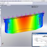
Due to the heavy load, the inadequate lubrication of the moving parts, and the complicated working environment of the press brake bending machine, it is very easy to cause the moving parts to wear or strain. This article will analyze the common mechanical failures and maintenance of hydraulic press bending machines:
Fault1. Long pause time for slider speed change point
1-1. The upper cavity of the cylinder sucks in air, and the pressure builds up for a long time (the self-priming pipeline leaks).
1-2. The flow rate of the filling valve or self-priming pipeline is small, or the sliding speed is too fast, causing needle suction.
1-3. The filling valve is not completely closed, and the pressure in the upper cavity slows down.
1-4. After the slow down valve is energized, close the filling valve and the upper cavity cannot suck oil.
1-5. The wrong position of the proportional valve leads to different openings and out of synchronization.
1-6. Decrease the fast-down speed to see if the test stops.
1-7. The size of the fast down pressure has an effect on the closing of the filling valve, and the fast down pressure is eliminated.
1-8. Adjust the pressure parameters in the delay stage before the work advance.
1-9. The damping hole of the filling valve control line is too small, forming a pressure difference.
1-10. CNC system parameters (delay before slow down).
1-11. CNC system parameters (the gain parameter decreases at a slower speed).
1-12. Check whether the oil level of the fuel tank is too low, the filling port is not flooded, and the upper cavity of the cylinder is filled with liquid during fast-forwarding, causing insufficient filling. For the above reasons, add oil from the tank to more than 5mm above the filling port so that the filling hole is completely flooded.
1-13. Check whether the filling valve is fully opened. If it is due to oil contamination, the valve core of the filling valve is not flexible and jammed, causing insufficient filling. Need to clean the filling valve and reinstall it to make the spool flexible.
1-14. Check whether the fast forward speed is too fast, causing insufficient filling. For the above reasons, the fast forward speed can be reduced by modifying the system parameters.
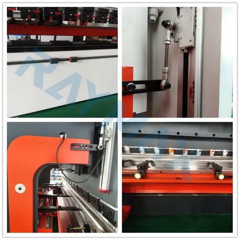
Fault2. When the slider is working, the downward direction is not vertical and abnormal noise.
This type of failure is due to a long time of use of the guide rail, abnormal lubrication of the guide rail, and increased clearance due to wear. It is necessary to check the wear degree of the guide rail pressure plate and readjust it to meet the required clearance. Determine whether to replace the guide rail pressing plate according to the degree of wear. If the strain is severe, it needs to be replaced.
2.1. The original pressure plate is pasted with plastic. Pay attention to the hardness of the pasted plastic and the pasting surface of the guide rail. After scraping, ensure that the pasting surface is above 85% and open a zigzag lubricating oil tank.
2.2. Inside the original pressing plate is a metal stopper. To choose a tin bronze plate or ductile iron, the bonding surface is processed by a grinder, the connecting bolt is lower than the bonding surface, and the zigzag lubricating oil groove is opened.
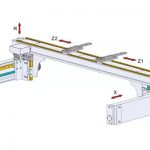
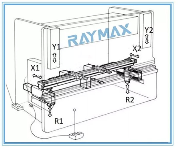
Fault 3. The size of the back gauge is inconsistent at both ends
The error at both ends is small, within 2mm. Check to confirm that the X1/X2 mechanical transmission structure has no faults. The error can be eliminated by adjusting the finger. If there is no fault in the mechanical transmission structure (such as bearings, ball screws, linear rails, transmission wheels, transmission belts, etc.), remove the fault. Re-adjust to within the tolerance of parallelism and re-install the synchronous transmission device.
Fault 4. No movement of the rear gear shaft at both ends
The reason for the failure of the backgauge shaft transmission may be that the transmission shaft is separated from the timing belt wheel, the key bar, or the timing belt slips off. The stopper shaft driver and servo motor are faulty, and the upper computer control system is faulty. Such failures need to check and confirm the cause of the failure, repair or replace the failed components and eliminate the failure.
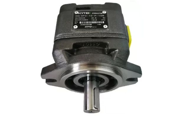
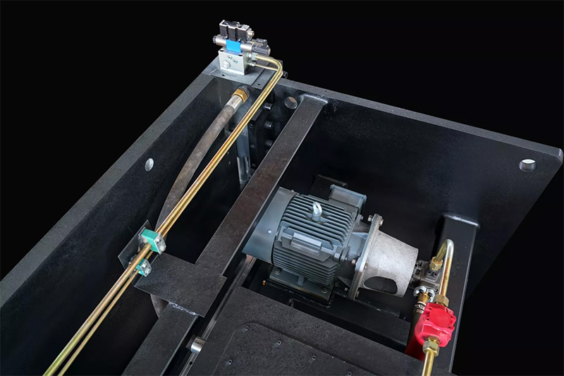
Fault 5. Excessive noise of the oil pump (too fast heating), damage to the oil pump
5-1. The oil pump suction line leaks or the oil tank liquid level is too low, causing the oil pump to empty.
5-2. The oil temperature is too low and the oil viscosity is too high, resulting in high oil absorption resistance.
5-3. The suction port oil filter is clogged and the oil is dirty.
5-4. The pump is damaged (injured when the pump is installed) by any knock.
5-5. Coupling installation problems, such as excessive axial tightening, the motor shaft, and the oil pump shaft are not concentric.
5-6. After the pump is installed, it reverses for a long time or does not refuel during the test machine.
5-7. The outlet high-pressure oil filter is blocked or the flow rate is not up to the standard.
5-8. The oil pump sucks (there is oil, but there is air at the oil pump suction port).
5-9. If it is a plunger pump, the height of the oil return port line may be set too low.
5-10. If it is a HOEBIGER oil pump, it may be deflated.
5-11. The oil temperature is too high, causing the viscosity to decrease (within 60°C).
5-12. Hydraulic oil contains water, which can cause blockage and damage to the high-pressure filter element.
Fault 6. No slow down the movement of the slider
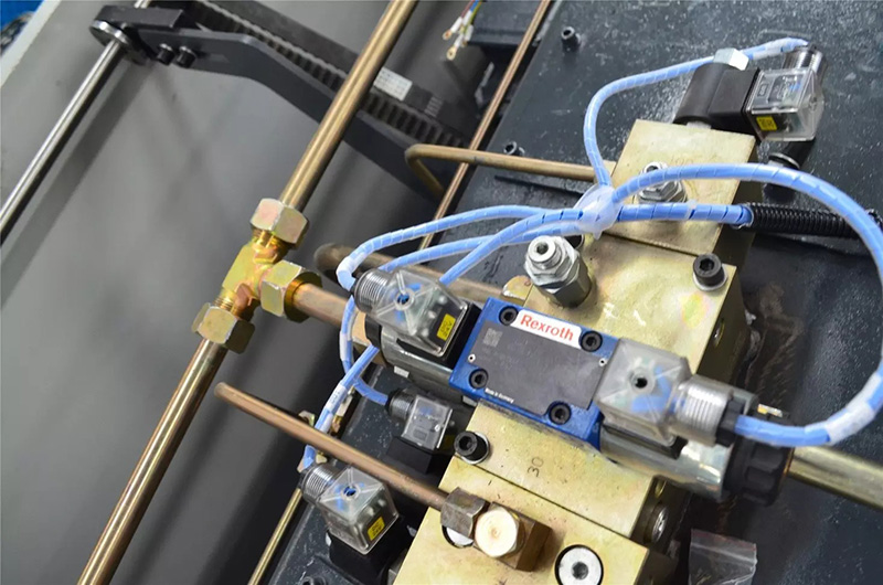
6-1. Whether the electromagnetic proportional directional valve has an electrical signal or whether the spool has any action or is stuck.
6-2. The system cannot build pressure.
6-3. The filling valve is stuck, or the filling valve sealing ring leaks.
6-4. Whether the slow valve has an electrical signal or is stuck.
6-5. Back pressure is too high or slows down pressure is too low.
Fault 7. When the slider moves slowly, it vibrates, swings, and makes noise
7-1. The pressure oil discharged from the cylinder contains air bubbles.
7-2. The friction force of the slide rail is too large, whether there is lubricating oil.
7-3. The gap between the fitting surface of the guide plate is large, or the top and bottom are uneven.
7-4. The level of the rack and workbench is not adjusted properly.
7-5. The balance valve is blocked.
7-6. Check if the quick-release valve is energized and opened.
7-7. The numerical control system parameter (gain), or the work feed speed setting is too large.
7-8. The backpressure valve is loose and the resistance on both sides is different.
7-9. Whether the solenoid proportional valve coil is biased and whether the neutral position signal of the proportional valve is correct.
7-10. Whether the signal of the proportional servo valve is disturbed, the inspection method is the same as above.
7-11. The piston rod is locked tightly by the oil cylinder sealing ring, and the resistance is large (change the PTFE hard sealing ring test).
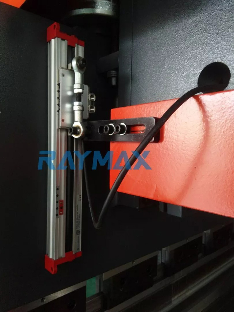
7-12. The spherical washer on the grating ruler is not installed, the sliding seat does not move smoothly, and there is a problem with the grating ruler communication line.
7-13. The pressure curve is wrong, the pressure is not enough during work.
7-14. The pressure sealing O-ring of the filling valve produces a small amount of leakage.
Fault 8. Large synchronization deviation when slowing down
8-1. Synchronous detection system failure (grating scale).
8-2. Proportional directional valve.
8-3. Leakage of quick lower valve.
8-4. The large gap in back pressure on both sides.
8-5. The oil temperature is too low.
8-6. Oil string in the upper and lower chambers of the cylinder.
8-7. CNC system parameters.
Fault 9. Bending angle error
9-1. Check whether the compensation deflection of the compensation cylinder is large and the zero position cannot be completely restored.
9-2. Check whether the quick-clamp is loose.
9-3. Check whether there is any change in the bottom dead point of each bending.
9-4. Check whether the bow-shaped plate is installed properly and whether the screw hole is dead.
9-5. Changes in the sheet itself (thickness, material, stress).
9-6. Is the grating ruler loose?
9-7. Inaccurate positioning accuracy: Is the zero offset value of the proportional valve appropriate? The positioning cannot reach the bottom dead center, making it impossible to return.
Fault 10. Oil leakage in hydraulic lines or tubing burst
10-1. Check whether the oil pipe installation meets the requirements (extended length, pipe diameter, wall thickness, ferrule, the nut is too tight, too loose, bending radius, etc.).
10-2. Whether the tubing has impact or vibration.
10-3. Check whether the pipeline interferes or collides with other.
10-4. The pipeline is not fixed by pipe clamps.
Fault 11. Precautions during hydraulic system installation and maintenance
11-1. The valves sealed with paint shall not be disassembled by themselves, let alone adjusted.
11-2. The valve works normally after cleaning, it must be replaced with new oil and cleaned the oil tank immediately.
11-3. The oil pump shall not be subjected to any knocks or impacts during installation, and the oil pump must be refueled before testing.
11-4. When installing each valve, only its valve body can be transported, and no solenoid valve should be touched.
Related Products
 Why Add a Compensation System to a Press Brake Bending Machine
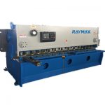
- How to Operate the Guillotine Shearing Machine
- 6 Tips about Laser Antifreeze
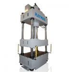
- Common Faults and Troubleshooting Methods of 100t Four-column Hydraulic Press
- How Many Types Of Hydraulic Press Brake
- The Working Principle and Composition of CNC Press Brake Bending Machine
- Common Faults and Troubleshooting Method for Four-column Hydraulic Press
- Safe Operation Rules of Hydraulic Power Press Machine
- How to Make Deflection Compensation for CNC Sheet Metal Bender
- What Are Press Brake Dies Made Of? What Is Press Brake Tooling?